

What is upstream and downstream bioprocessing?
At TECNIC, we possess a deep understanding of both upstream and downstream processes, crucial for biotechnological product development. Therefore, this article aims to illustrate their differences and highlight their significance in biotechnology.
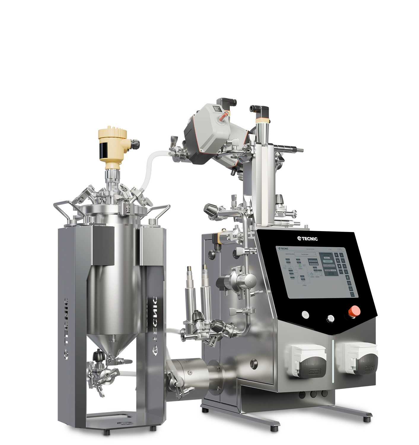
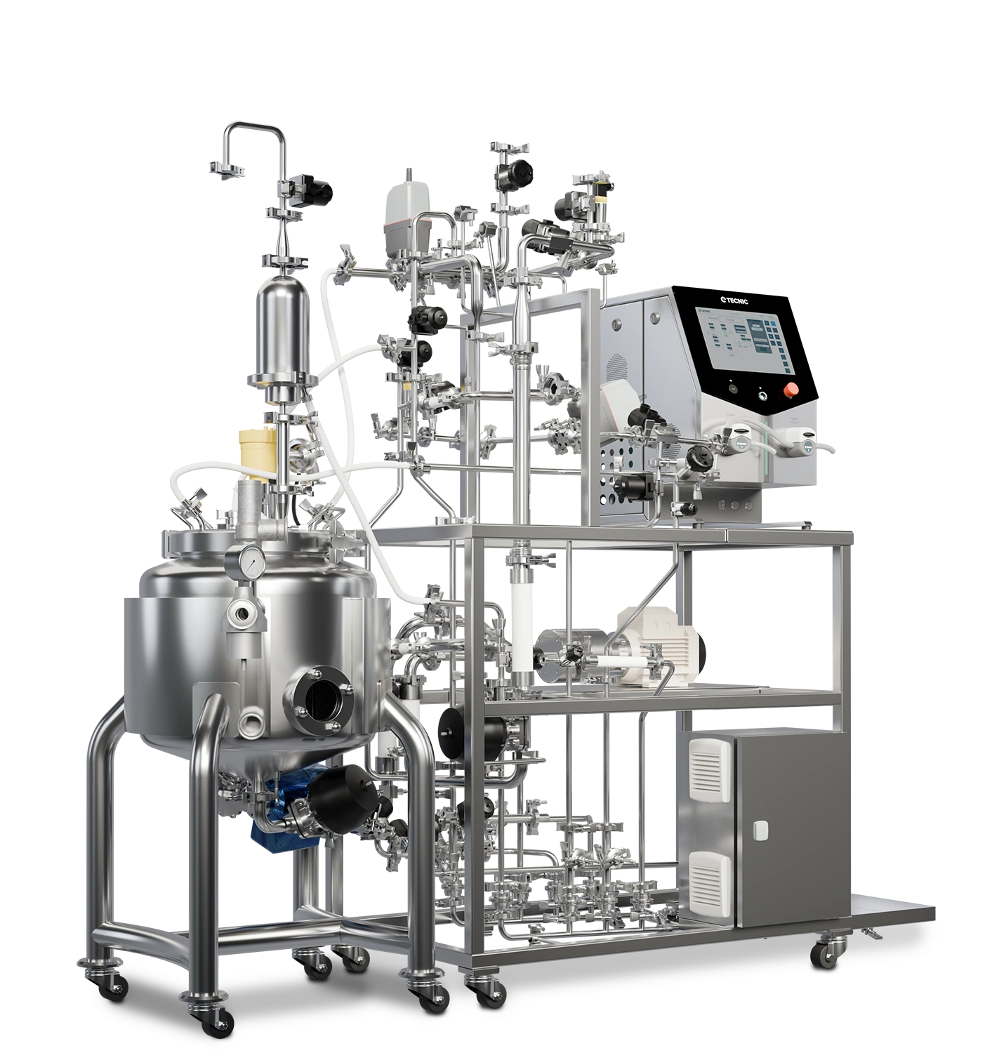
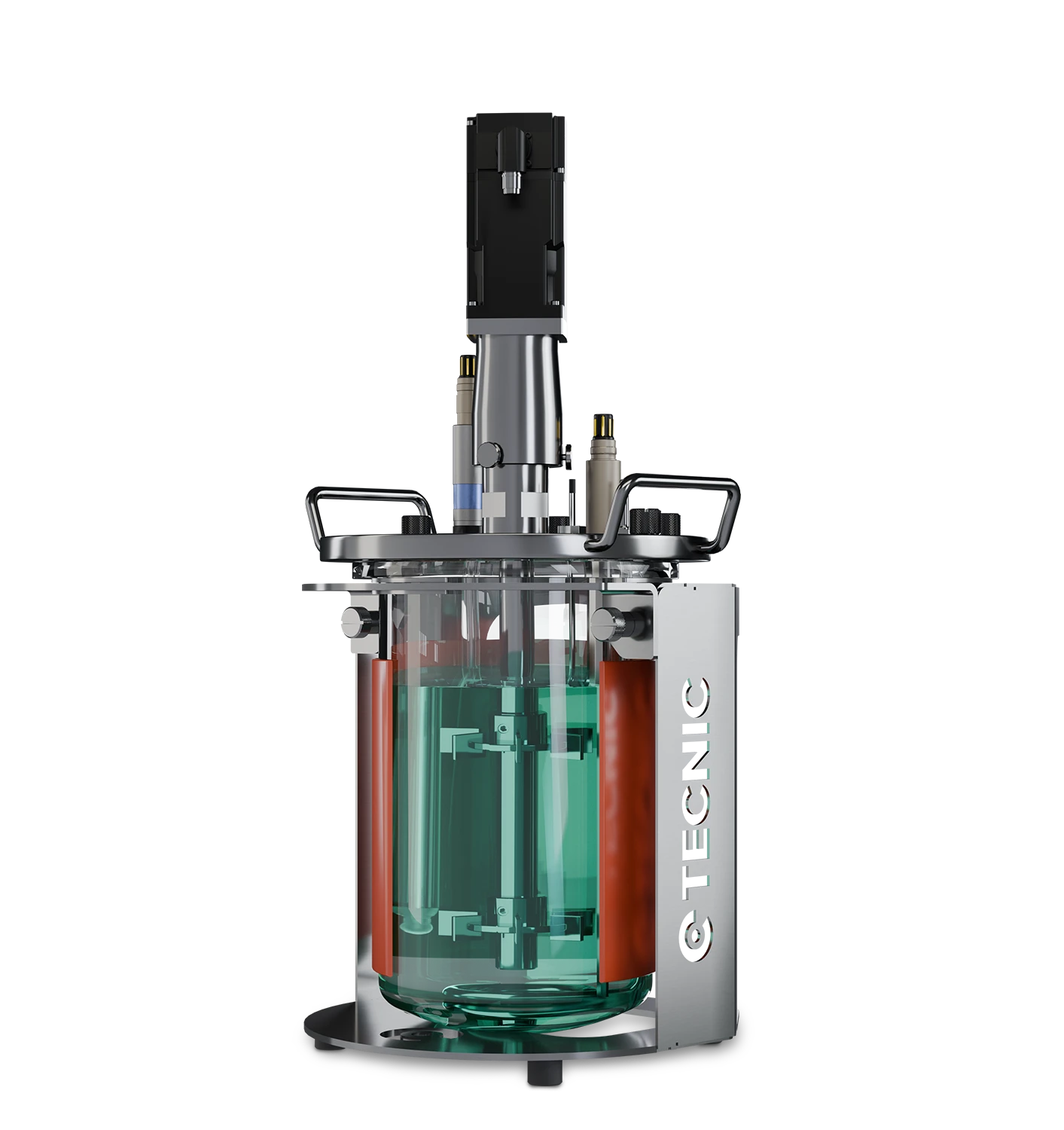
What is an upstream bioprocessing?
The upstream process in bioproduction is akin to the stage in a cell culture laboratory where optimal conditions are prepared for cell growth and multiplication.
In a laboratory, before any cell experiment can be conducted, it is crucial, therefore, to prepare a conducive environment for their growth. This involves preparing a nutritious culture medium, adjusting temperature conditions, and ensuring that the cells have the space and resources necessary to grow and multiply.
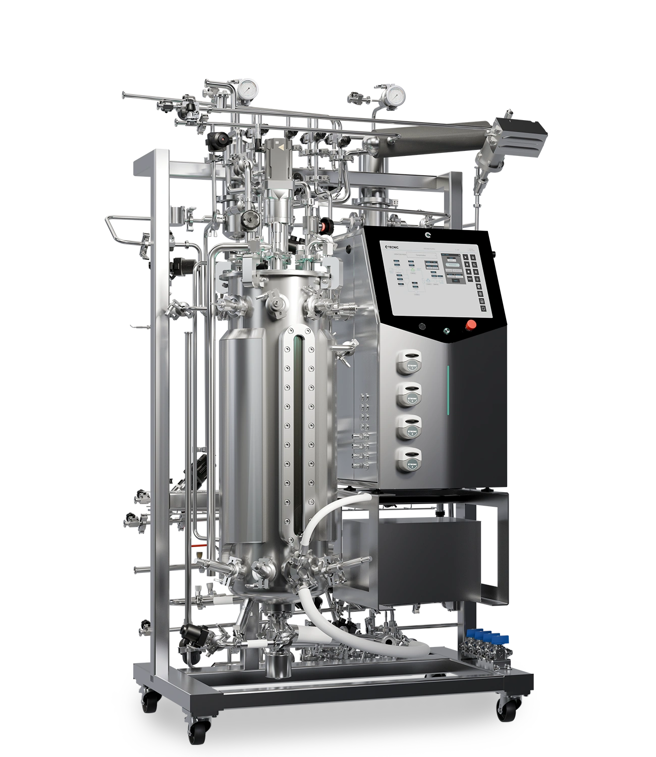
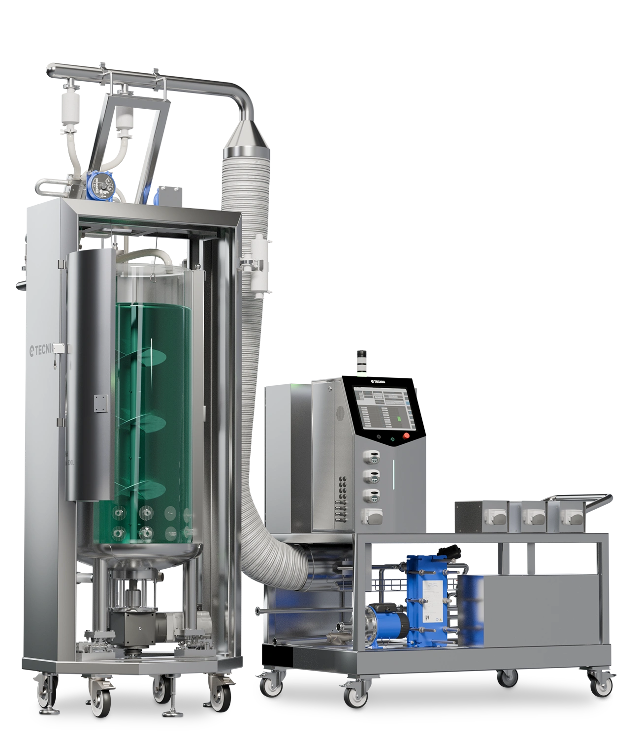
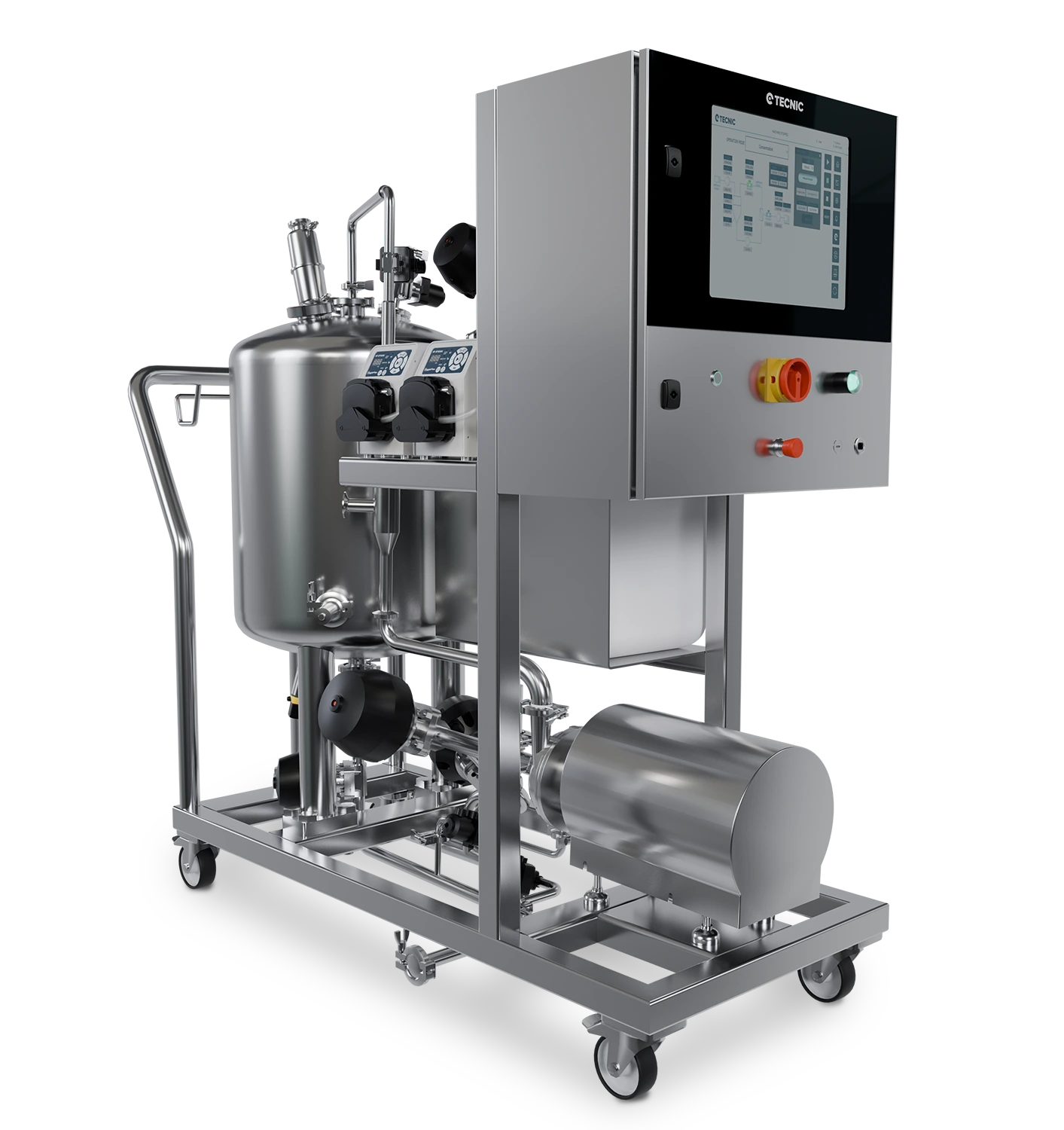
Similarly, in the upstream bioprocessing in bioproduction, the necessary raw materials, in this case, microorganisms, are prepared and cultivated. The goal is to create a conducive environment for their growth and multiplication. This bioprocess includes preparing the culture medium, inoculating with the desired microorganisms, and managing growth conditions like temperature, pH, and aeration, among others, to secure the desired product quality and yield.
Just as in the cell culture laboratory, where a controlled and favorable environment for cell growth is established, the upstream bioprocess optimizes conditions for microorganism growth and the production of desired biotechnological products. This bioprocess is crucial for ensuring the final product's desired quality and yield.

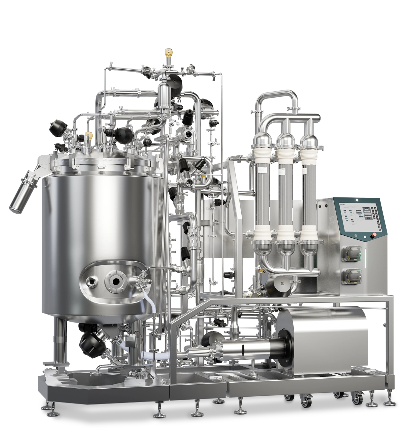
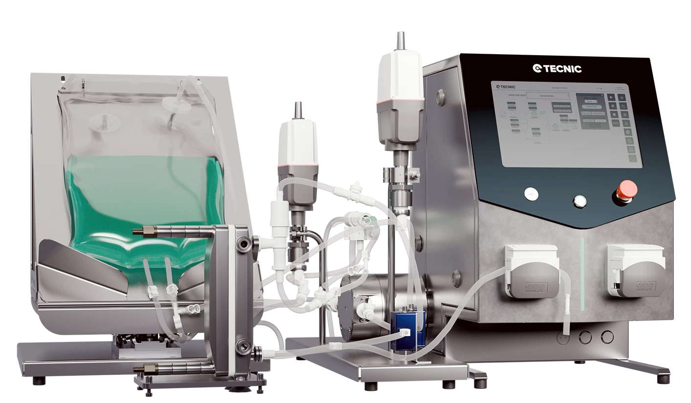
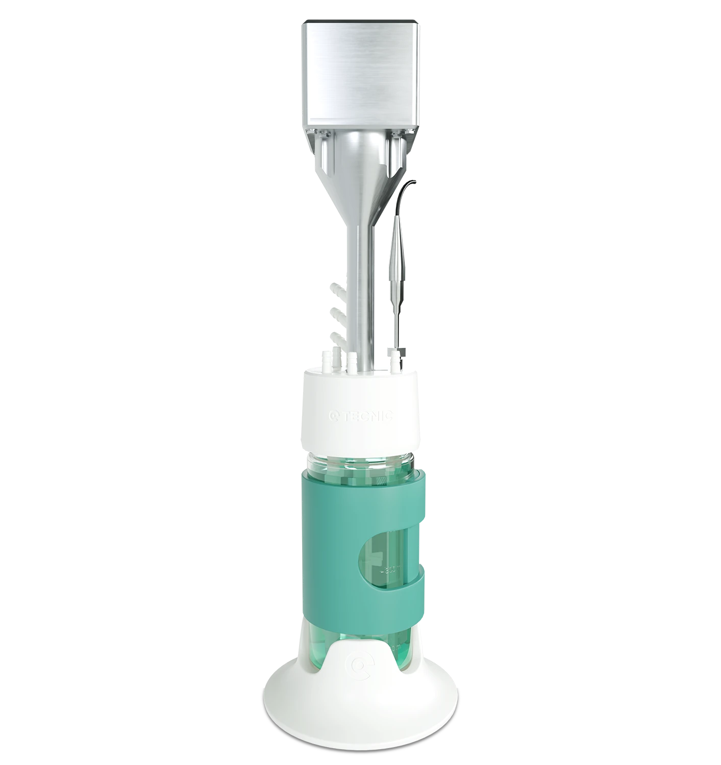
What is a downstream bioprocessing?
The downstream process in bioproduction closely resembles a chemical laboratory's stage where the goal, following a series of chemical reactions, is to isolate and purify the desired compound from the mixture’s other compounds and impurities.
In chemical laboratories, after completing a reaction, techniques like filtration or distillation separate and purify the compound of interest. For example, achieving a specific chemical compound necessitates separating desired reaction products from undesired ones and impurities.
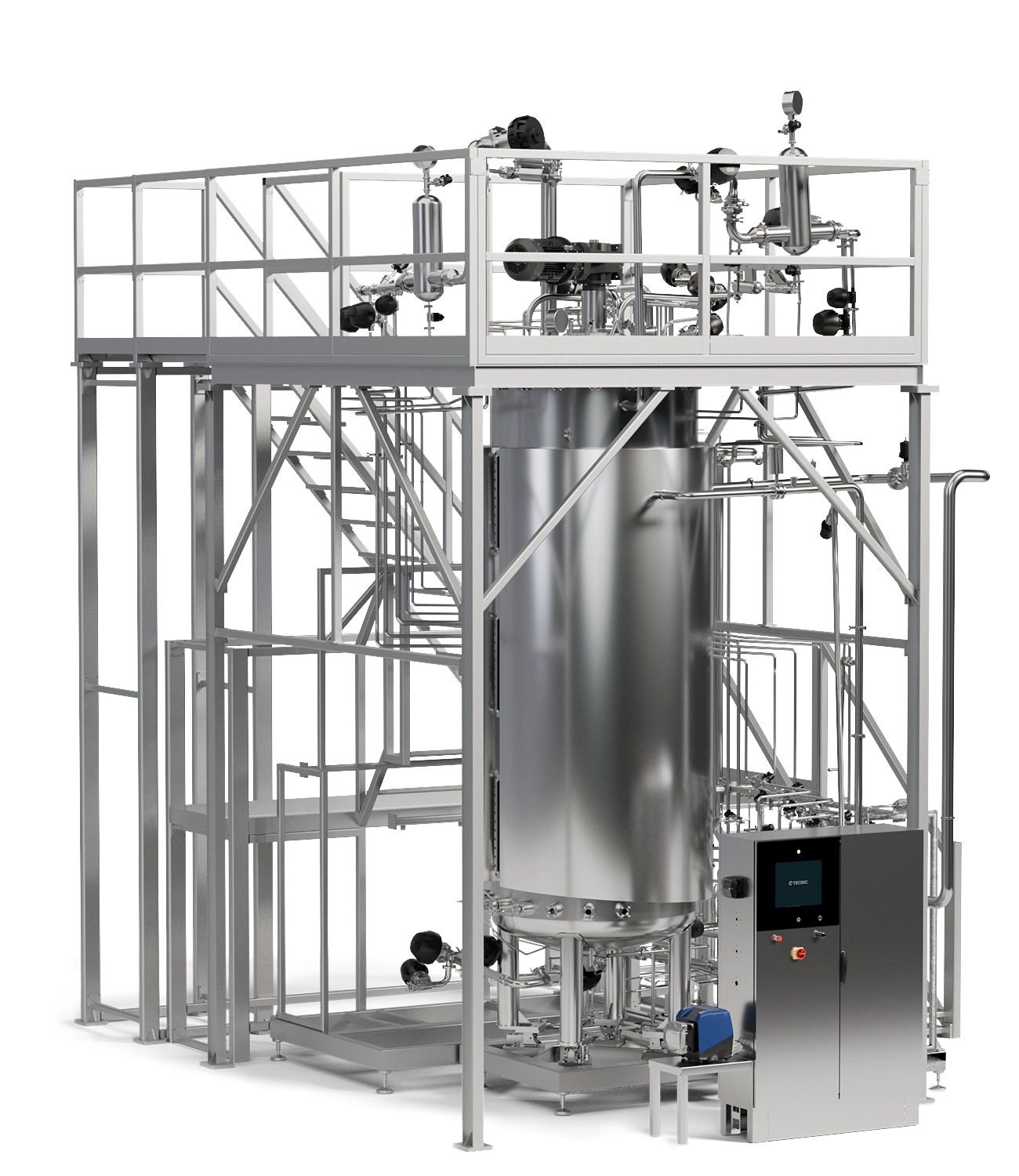
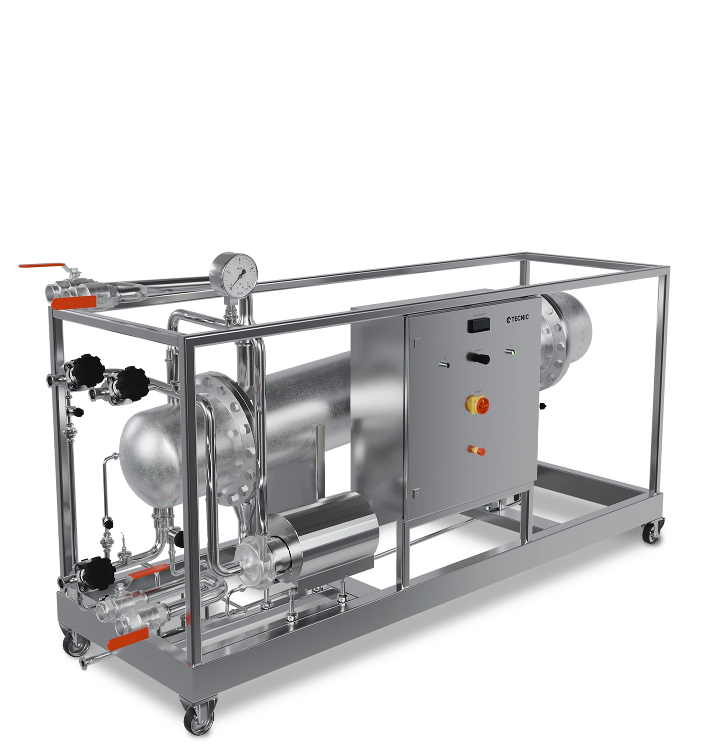
Similarly, bioproduction's downstream bioprocess entails separating, purifying, and concentrating the product microorganisms created during the upstream bioprocess. Consequently, using filtration techniques, this stage effectively isolates biotechnological products from impurities and other microbial culture components, yielding a purified, concentrated product ready for use or commercialization.
Just as achieving a pure compound is the aim in a chemical lab, the downstream bioprocess in bioproduction seeks to produce a biotechnological product of high quality, with suitable purity and concentration, thereby preparing it for its final application or further stages of processing and analysis.


Conclusions
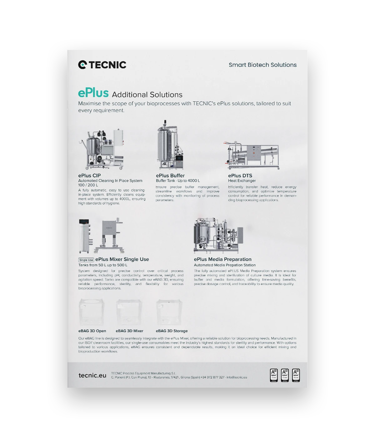
Understanding the differences between upstream and downstream processes is crucial for bioproduction excellence. At TECNIC, we are dedicated to enhancing bioprocess efficiency and product quality within the biotech industry. Consequently, we invite you to visit our website and explore our wide range of services and solutions ⇀ , all designed to meet modern bioproduction demands.


Frequently Asked Questions (FAQ)
The upstream bioprocessing is the stage in biotechnology production where micro-organisms are prepared and cultured under optimal conditions for growth and multiplication. This includes preparation of the culture medium, inoculation with desired micro-organisms and management of growth conditions such as temperature, pH and aeration.
The downstream bioprocessing is the biotechnological production step where the desired product is separated, purified and concentrated from the micro-organisms and other impurities produced during the upstream bioprocess. Filtration, centrifugation and other techniques are used to obtain a pure and concentrated biotech product.
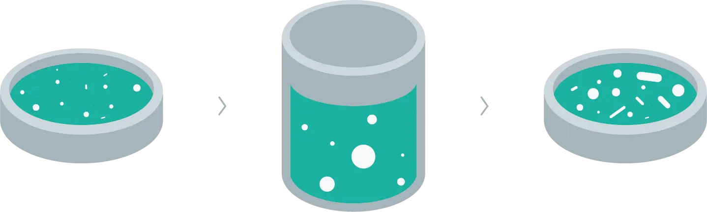
In biotechnology, upstream processing focus on the cultivation and growth of microorganisms or cells, while downstream processes focus on the separation, purification and concentration of the final product.
The upstream and downstream processing complement each other by providing a continuous flow from the cultivation and growth of microorganisms to the production of a purified final product. Each stage is dependent on the other to ensure that the entire process is efficient and produces a high quality result.
Upstream and downstream processing are crucial to ensure the desired quality and yield of the final product in biotechnology. These processes optimise conditions for microbial growth and production of biotech products, and then purify and prepare these products for final application or further processing and analytical steps